Chat with us, powered by LiveChat

Technical Cable Applications Blog

usb cable types

How to Identify USB Cable Types

In today’s gadget-driven world, USB cables have become an indispensable part of our daily lives. From charging smartphones to connecting devices, these cables vary widely in shape, size, and function. This guide will illuminate the visual differences and uses of the most common USB cable types, ensuring you select the right cable with ease whether you’re just trying to purchase the right one for your personal needs, or if you’re in need of bulk USB cable assembly manufacturing for industrial or business applications. If the latter applies to you and you need a reliable cable manufacturing partner, please contact us at [email protected] with your cable drawing and required specifications!

Most Common USB Cable Types Explained

1. USB-A

Visual Identification: The quintessential USB connector, USB-A is a flat and rectangular plug that’s often found at one end of most USB cables. It usually connects to host devices such as computers or power outlets.

Introduction and Use: Introduced in the mid-1990s, USB-A remains the standard for connecting peripherals like keyboards, mice, and external storage devices. Commonly used for data transfer as well as charging, it supports data transfer rates of up to 480 Mbps for USB 2.0 versions and up to 5 Gbps for USB 3.0.

usb-a

2. USB-B

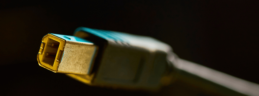
Visual Identification: USB-B connectors are noticeably square with beveled corners on the top. They are less common in consumer electronics and are often seen connecting to larger devices like printers and scanners.

Introduction and Use: Around since the original USB standard, USB-B is primarily used for data transfer and charging larger devices. With USB 3.0 variations, identifiable by additional pins and often a blue internal color, data transfer speeds can reach up to 5 Gbps.
usb-b

3. USB-C

Visual Identification: Featuring a small, sleek, and oval design, USB-C is reversible, meaning it can be plugged in either way without issue—an ergonomic advantage.

Introduction and Use: Introduced in 2014, USB-C has quickly become the universal standard in modern devices, prevalent in smartphones, laptops, and tablets for both data transfer and charging. It supports up to 10 Gbps for USB 3.1, speeds of 20 Gbps for USB 3.2, and is capable of 40 Gbps with Thunderbolt 3 and 4 technology.

usb-c

4. Mini-USB

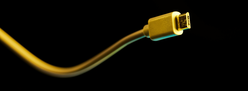
Visual Identification: Mini-USB comes in a smaller size than USB-A or USB-B, with a trapezoidal shape. It’s typically found in old models of MP3 players and cameras.

Introduction and Use: Common in the early-to-mid 2000s, mini-USB served for connecting smaller personal electronics and offered 480 Mbps data transfer rates like USB 2.0.
mini-usb

5. Micro-USB

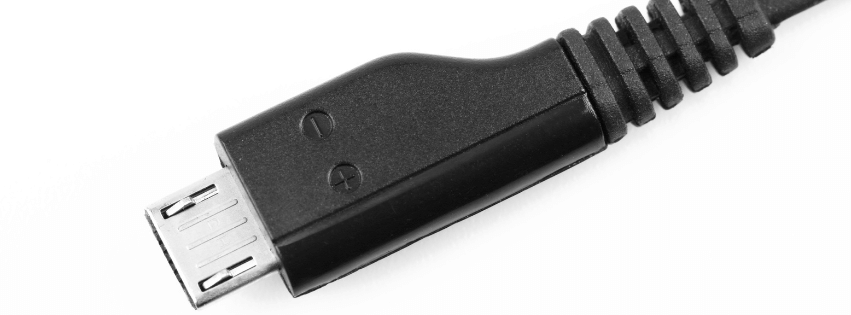
Visual Identification: A more compact connector than mini-USB, micro-USB has a flatter and narrower form, and is somewhat trapezoidal with a wider top.

Introduction and Use: Released in the late 2000s, micro-USB became the standard for older Android phones and various portable devices, offering data speeds up to 480 Mbps (USB 2.0) and charging capacities.
micro-usb

Exploring Lesser-Known USB Variations

While the more common USB types tend to dominate the scene, it’s important to also recognize some of the less common variants. These connectors cater to specific devices and uses, and understanding them can offer a complete picture of the USB landscape.

1. USB-A SS (SuperSpeed USB-A)

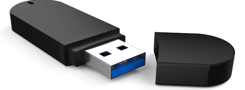
Visual Identification: A step up from the traditional USB-A, the USB-A SS connector can often be identified by a blue color inside the port (though this isn’t always the case). The external shape remains the same as the standard USB-A.

Introduction and Use: As part of the USB 3.0 standard introduced in 2008, USB-A SS supports faster data transfer speeds of up to 5 Gbps. This variant is used extensively in devices that require rapid data transmission, such as external hard drives and Solid-State Drives (SSDs), allowing for efficient data backups and file transfers.
usb-a ss

2. USB Mini-B

Visual Identification: The USB Mini-B connector resembles the mini-USB type with its slightly trapezoidal shape, yet it contains an additional pin compared to the standard mini-USB.

Introduction and Use: Often found in older camera models and some legacy mobile devices, this connector type was popular in the early 2000s. While being largely phased out in favor of micro-USB or USB-C, mini-B was pivotal for synchronizing and charging smaller electronics at data rates up to 480 Mbps.

mini b

3. USB 4-Pin

Visual Identification: The USB 4-pin looks like a simplified version of the larger USB connectors, often used in uncommon situations to deliver specific functions. It lacks the notch and traditional USB housing seen in other types.

Introduction and Use: It’s typically seen in proprietary systems or specialized applications, providing both power and data transfer but at limited rates compared to mainstream USB styles. Primarily, its function depends on the device it was designed for, making it less adaptable.

usb 4 pin

4. Micro-B and Micro-B SS (SuperSpeed Micro-B)

Visual Identification: The Micro-B connector is quite similar to micro-USB but has a slightly different pin setup, with additional connections visible. The SuperSpeed Micro-B variant is known for its bifurcated form: one standard micro-USB side and an additional smaller pin section.

Introduction and Use: Micro-B was primarily used in smartphones and tablets before USB-C standardization. With the advent of formats like USB 3.0, the Micro-B SS version found its place in external hard drives, enabling SuperSpeed data transfers up to 5 Gbps, thereby enhancing external storage performance considerably, before being mostly replaced by the more ergonomic and faster USB-C.
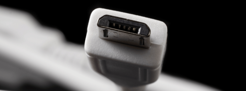
usb micro b

Specifications and Usability

Knowing your USB cables doesn’t just help in identifying them visually, but also helps understand their specifications regarding data transfer and usage contexts. USB 2.0, 3.0, and beyond vary in their data transfer capabilities, where higher versions offer backward compatibility but greatly increase transfer rates. Understanding these distinctions can help in choosing the right cable for either transferring files or efficiently charging a device.

Conclusion

Understanding USB cable types can simplify connecting your devices, maximizing performance, and ensuring compatibility. Whether you’re a tech enthusiast or simply dealing with the cords that power your world, knowing which cable goes where is invaluable.

At Technical Cable Applications, we specialize in the bulk manufacturing of a wide range of cable assemblies, from USBs to other essential data and power solutions like Ethernet, M12, and coaxial cables. We hope this guide serves your needs and helps you navigate the vast landscape of USB technology with confidence. If you’re in need of USB cable assembly manufacturing for your business, government or industrial needs, please contact us at [email protected] with your cable drawing and any necessary NDAs!
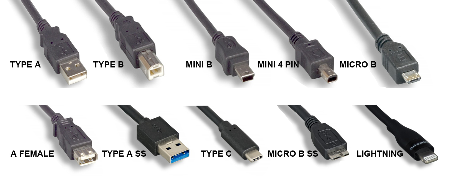
USB cable assemblies with USB-A and USB-B connectors

USB Cable Assemblies: A Guide to Connectors, Standards, and Construction

A USB cable assembly is a finished cable built to a USB specification, with a connector on each end, that carries data, power, or both between devices. USB cable assemblies are in nearly every product category, from consumer electronics to medical devices, industrial controls, and test equipment. Choosing the right one means matching the connectors, the USB data rate, the length, the current rating, and the cable’s construction to where it will be used.

This guide covers how USB cable assemblies are built, the USB standards and connector types in use today, length and power limits, and what to specify when you order a custom assembly. Technical Cable Applications (TCA) manufactures custom and OEM USB cable assemblies, from Type-A to USB-C.

What Is a USB Cable Assembly?

“USB cable” and “USB cable assembly” often mean the same thing. In manufacturing, “assembly” stresses that the product is built from separate parts: bulk cable, connectors, and the molding or hardware that joins them. It’s terminated and tested as a finished unit.

An off-the-shelf USB cable is a fixed design: standard connectors, a few stock lengths, a general-purpose jacket. A custom USB cable assembly is built to a drawing. The buyer specifies the connector ends and orientation, exact length, wire gauge, shielding, jacket material, overmold shape, labeling, and testing. OEMs use custom assemblies when a stock cable is the wrong length, won’t fit the enclosure, can’t survive the environment, or needs a connector combination nobody stocks.

Components of a USB Cable Assembly

Each end has a plug (male) or receptacle (female) in one of the USB connector families: Standard-A, Standard-B, Mini-B, Micro-B, or USB Type-C. The connector determines which ports the cable fits and limits which USB data rates it can support. USB-C is the only connector that supports USB 3.2 Gen 2×2 (20 Gbps) and USB4.

Conductors

The wires inside depend on the USB version the cable supports:

  • USB 2.0: four conductors: VBUS (+5 V power), ground, and a twisted data pair (D+ and D−). The data pair is designed for 90 Ω differential impedance. Data wires are typically 28 AWG. Power wires range from 28 AWG to 20 AWG, and a heavier gauge allows a longer cable or more current.
  • USB 3.x on Standard-A, Standard-B, or Micro-B: the four USB 2.0 conductors plus two shielded SuperSpeed differential pairs (one transmit, one receive) and a drain wire.
  • USB-C to USB-C: a full-featured cable adds four high-speed differential pairs plus the configuration channel (CC), sideband use (SBU) lines, and VCONN, which powers the electronic marker chip described below. A USB 2.0-only USB-C cable leaves out the high-speed pairs.

Shielding

High-speed USB cables are shielded to contain electromagnetic interference (EMI) and protect the signal from outside noise. A common construction is an aluminum-foil shield under a tinned-copper braid, with a drain wire bonded to the connector shell. SuperSpeed pairs are usually shielded individually as well. Shielding matters more in electrically noisy places such as factories, near motors and drives, or around medical and RF equipment.

Jacket

The outer jacket protects the conductors from abrasion, chemicals, temperature, and flexing. PVC is the general-purpose standard. PUR (polyurethane) and TPE resist oil, abrasion, and repeated flexing better, which suits machinery and cable carriers. Low-smoke zero-halogen (LSZH) jackets are specified where smoke toxicity is a concern.

Overmold, Backshell, and Strain Relief

The joint between cable and connector is the most common failure point. Overmolding encases the termination in molded plastic to seal it and give it a shaped strain relief. Metal or die-cast backshells add mechanical strength and EMI protection, and some include thumbscrews or latches to lock the plug in place.

Electronic Marker (USB-C)

Many USB-C cables include an electronic marker (e-marker) chip that reports the cable’s capabilities, such as current rating and supported data rate, to connected devices. The USB Type-C specification requires an e-marker in cables rated for 5 A and in full-featured USB-C to USB-C cables. Without one, a device assumes the cable is limited to 3 A.

USB Standards and Data Rates

USB was introduced in 1996, and each major revision raised the maximum data rate. The USB Implementers Forum (USB-IF) has renamed several versions over time. For example, the original USB 3.0 has also been called USB 3.1 Gen 1 and USB 3.2 Gen 1. Since 2022, USB-IF has recommended that products be labeled by speed (“USB 5Gbps,” “USB 10Gbps,” and so on) rather than by version number.

Version (later names) Max data rate Speed-based label Connectors Year
USB 1.0 / 1.1 1.5 Mbps (Low Speed), 12 Mbps (Full Speed) n/a Standard-A, Standard-B 1996 / 1998
USB 2.0 480 Mbps (High Speed) n/a Standard-A/B, Mini, Micro, USB-C 2000
USB 3.0 (USB 3.1 Gen 1, USB 3.2 Gen 1) 5 Gbps USB 5Gbps Standard-A/B SuperSpeed, Micro-B SuperSpeed, USB-C 2008
USB 3.1 Gen 2 (USB 3.2 Gen 2) 10 Gbps USB 10Gbps Standard-A SuperSpeed, USB-C 2013
USB 3.2 Gen 2×2 20 Gbps USB 20Gbps USB-C only 2017
USB4 (Version 1.0) 20 or 40 Gbps USB 20Gbps / USB 40Gbps USB-C only 2019
USB4 Version 2.0 80 Gbps; up to 120 Gbps one way in asymmetric mode USB 80Gbps USB-C only 2022

USB 2.0 remains the most common interface for peripherals, sensors, and embedded devices that don’t need high bandwidth, because it’s inexpensive and tolerates longer cable runs. The 5 Gbps to 20 Gbps tiers cover storage, cameras, and docking. USB4 serves high-bandwidth uses such as external displays and fast storage.

USB Connector Types

The connector and the data rate are separate choices. A USB-C cable can be wired for USB 2.0 only or for USB4, so specify both. For help telling connectors apart by sight, see our guide on how to identify USB cable types.

Connector Versions Typical use today Introduced
Standard-A USB 1.x, 2.0; SuperSpeed version (9-pin) for USB 3.x Host side of most legacy cables: computers, chargers, hubs 1996
Standard-B USB 1.x, 2.0; SuperSpeed version for USB 3.x Printers, scanners, audio interfaces, instruments, industrial equipment 1996
Mini-B USB 2.0 Older cameras, GPS units, MP3 players; still found on some industrial and test equipment ~2000
Mini-A / Mini-AB USB 2.0 (On-The-Go) Rarely used; deprecated by USB-IF in 2007 ~2001
Micro-B USB 2.0; SuperSpeed version (10-pin, wider) for USB 3.x Older Android phones and accessories; Micro-B SuperSpeed on many external hard drives 2007
Micro-A / Micro-AB USB 2.0 (On-The-Go) Let a mobile device act as host; uncommon 2007
USB Type-C USB 2.0 through USB4; USB Power Delivery Current standard for phones, laptops, tablets, and new devices; reversible 2014

Apple’s Lightning connector (2012) isn’t a USB-IF connector, though USB-to-Lightning cables are common. Apple has moved its newer devices to USB-C, and since 28 December 2024 the EU has required USB-C charging ports on phones and many other portable devices sold there.

USB Cable Length Limits

Signal loss rises with frequency, so the faster the data rate, the shorter a passive cable can be. These are the usual limits for passive cables:

Cable type Typical maximum length
USB 2.0 (Standard, Mini, Micro connectors) 5 m
USB 3.x, Standard-A/B or Micro-B, 5 Gbps About 3 m in practice (the spec sets a loss budget, not a length)
USB-C to USB-C, USB 2.0 4 m
USB-C to USB-C, 5 Gbps 2 m
USB-C to USB-C, 10 Gbps 1 m
USB-C to USB-C, USB4 40 Gbps 0.8 m

USB-C lengths are the recommended maximums in the USB Type-C specification. Longer runs need active cables, which use electronics in the connector housing to regenerate the signal, or active optical cables (AOCs), which carry data over fiber. Powered hubs and repeaters are another option.

Power and Current Ratings

USB cable assemblies carry power as well as data, so the conductors have to be sized for the current.

  • Default USB power: 500 mA at 5 V for USB 2.0 ports and 900 mA for USB 3.x ports.
  • Battery Charging (BC 1.2): up to 1.5 A at 5 V from dedicated charging ports.
  • USB Type-C current: 1.5 A or 3 A at 5 V, advertised over the CC line.
  • USB Power Delivery (PD): negotiates higher voltages. Standard Power Range reaches 100 W (20 V at 5 A). Extended Power Range, added in PD 3.1 (2021), reaches 240 W (48 V at 5 A).

Every USB-C cable must handle at least 3 A. Delivering more than 60 W (above 3 A) takes a 5 A-rated cable with an e-marker. In a custom assembly, the power-conductor gauge, the cable length, and the allowable voltage drop are designed together.

Common USB Cable Assembly Configurations

  • Straight-through cables: a standard connector on each end, such as USB-A to USB-C or USB-A to Micro-B.
  • Right-angle and up/down-angle connectors: for tight enclosures and cable routing.
  • Panel-mount and bulkhead extensions: bring a USB port through an enclosure wall to a front panel.
  • Locking and screw-retention connectors: thumbscrews, latches, or threaded couplings keep the plug seated under vibration.
  • Sealed connectors: IP-rated USB connectors and sealed overmolds for washdown, outdoor, or dusty environments.
  • Y-cables and split cables: separate power and data, or feed power from two ports.
  • Adapter cables: USB to serial (RS-232/RS-485), USB to Ethernet, USB to HDMI, and other protocol converters.
  • Bare or pigtail ends: a USB connector on one end and stripped, tinned, or crimped leads on the other for wiring to a board or terminal block.

For machinery, automation, and other harsh environments, see our overview of industrial USB cables.

How to Specify a Custom USB Cable Assembly

A complete specification avoids rework and gets an accurate quote faster. Define the following:

  1. Connector ends: connector type, gender, and orientation (straight, right-angle) for each end.
  2. USB version and data rate: USB 2.0, 5/10/20 Gbps, or USB4. This sets the conductor count and shielding.
  3. Length and tolerance: keep within the limits above, or plan for an active solution.
  4. Current and voltage: the maximum current and whether USB Power Delivery or an e-marker is needed.
  5. Wire gauge: especially for the power conductors on longer cables.
  6. Shielding: foil, braid, or both, and how the shield terminates to the connector shell.
  7. Jacket: material (PVC, PUR, TPE, LSZH), color, outer diameter, and flex requirements.
  8. Environment: temperature range, chemical or oil exposure, UV, moisture or ingress rating, and vibration.
  9. Termination and strain relief: overmold shape, backshell, locking hardware.
  10. Compliance: for example RoHS, REACH, UL listing, or USB-IF certification if the product will carry USB logos.
  11. Labeling and packaging: part-number labels, heat-shrink markers, bagging, and coiling.
  12. Testing: the electrical tests required and any documentation that must ship with each lot.
  13. Quantity: prototype, pilot, and production volumes.

A drawing with the full pinout is the fastest route to a quote. Learn more about TCA’s custom USB cable assemblies.

Testing and Quality

USB cable assemblies are usually tested for continuity, opens, and shorts on every conductor. Many specifications add insulation resistance or hipot testing. High-speed assemblies may also need signal-integrity testing, such as differential impedance, insertion loss, and crosstalk, to confirm the cable meets its data rate at its length. Products that will display USB-IF logos must pass USB-IF compliance testing.

TCA is ISO 9001:2015 certified for custom and OEM cable assembly, and holds UL cable assembly certification for the United States and Canada.

Custom Requirements

In addition to our OEM offerings, Technical Cable Applications’ skilled specialists are ready to help with any custom cable assembly requirements you might have. TCA stocks cables, connectors, and materials by the thousands and can custom build dies and molds not on hand.

Please contact the TCA Technical Sales Team for assistance with all your cable assembly needs by reaching out to [email protected] or giving us a call!

*Please provide cable drawings and all documentation available when contacting us so we can quickly give you an accurate quote. We will do our best to research specifications and materials if a drawing is not available, but if no documentation exists that may need to be created first before we can proceed.

The Evolution of Cable Assembly Manufacturing

The Evolution of Cable Assembly Manufacturing

Complexity in cable assembly manufacturing grows incessantly, compelling producers to grapple with intricate designs, precise specifications, and relentless pressure to optimize productivity, while maintaining the quality at the highest possible standard.

Innovation is the linchpin.

Adopting advanced manufacturing technologies and methodologies, including work instruction software, streamlines processes and enhances efficiency, meeting the demands of an ever-evolving industry.

From Handcrafting to Automation

Though cable assembly manufacturing can be an extremely labor-intensive process, cable assemblers are integrating sophisticated automation technologies that bolster consistency, minimize human error, and accommodate the complexities of modern cable assembly production. This evolution supports the aspirations of assemblers and fabricators for heightened productivity, paving the way for unprecedented levels of innovation and customer satisfaction.

Early Manual Techniques

In the initial stages of cable assembly manufacturing, each connection was carefully made by hand. This process was not only time-consuming but also required a high degree of skill and precision, restricting production capacity.

Operators used an array of hand tools, like wire strippers and soldering irons, to assemble cables. Each wire had to be cut, stripped, and soldered or crimped individually, leading to lengthy production cycles.

Early cable manufacture was a meticulous artisanal craft that relied on the steady hands and keen eyes of experienced workers.

Despite advances, these manual techniques established foundational skills and standards that persist in the industry. They underscored the necessity for precision and the value of craftsmanship in creating reliable connections. This groundwork shaped the evolution toward mechanization and automation.

Introduction of Semi-Automated Processes

The advent of semi-automated technologies marked a significant milestone in cable assembly manufacturing, fostering efficiency and consistency.

  1. Implementation of Cutting Machines streamlined the wire cutting process, reducing the variability inherent in manual cutting.
  2. Crimping Machines advanced from manual to pneumatic and eventually semi-automatic operation, enhancing connection uniformity.
  3. Pre-Programmed Stripping Machines offered precise insulation removal, mitigating the risk of wire damage.
  4. Automatic Soldering Stations provided consistent solder joints while minimizing the potential for human error.
  5. Work Instruction Software began guiding operators through the production process, ensuring adherence to specifications and minimizing deviations.

With these machines, operators could oversee multiple stages simultaneously, substantially increasing throughput without sacrificing quality.

Investments in semi-automated systems allowed for scalable production capacities, aligning with the burgeoning demand for cable assemblies across various industries.

The Digitalization Impact

The advent of digital technology has marked a significant transformation in cable assembly manufacturing, introducing a new epoch characterized by unparalleled precision and efficiency. Within this digital realm, work instruction software has emerged as a cornerstone, effectively revolutionizing the transmission of intricate assembly knowledge. By digitizing and centralizing instructions, this software mitigates the risk of human error, propelling the industry towards a future where consistency and quality are augmented by an unwavering adherence to detailed digital directives. Consequently, assemblers and fabricators are empowered to exceed customer expectations with every meticulously crafted product.

Future Trends

Advanced materials, including high-performance polymers, will revolutionize the durability and functionality of cable assemblies, shaping customer expectations.

Connected and automated manufacturing processes, leveraging technologies like Artificial Intelligence (AI) and the Internet of Things (IoT), will drive efficiencies and elevate the precision and scalability of cable assembly production, meeting the upsurge in demand for increasingly complex systems.

Digital twin methodologies and predictive maintenance will emerge as standard practices, enhancing product lifecycle management and operational reliability.

How Do We Make Cable Molds?

Cable molding is used for all sorts of power and data transmission cables, and is more prevalent than the average consumer might realize. For instance, many consumer grade HDMI and USB cables have basic molding included to provide protection during connection and disconnection.

If molding is so commonplace nowadays, one might ask, then why are we writing about it? To put it simply, there are a great number of styles of cable molding that differ a lot from each other in terms of usage, and the manufacturing process. The basic molding you’ll find on many consumer grade cables is not sufficient for all applications so overmolded, industrial strength and custom molded cables are needed in many instances. We’ll describe the general molding manufacturing process that we use, and how we customize cable molding for customers based on their requirements and needs here.

Cable Molding Manufacturing
The simplest explanation of how cable molding is made, is that pressure is used to force material into a mold cavity or what we typically call a “die”, with the desired shape the final mold needs to be. Molding machines automate and simplify this process. We use MoldMan thermoplastic machines to overmold cables by the thousands at Technical Cable Applications. We use special thermoplastic material, such as the polyamide Macromelt OM 646, and heat it to up to 475 degrees Fahrenheit depending on what the final molding needs. Our MoldMan machines allow us to time the injection and clamping processes perfectly with up to 2 tons of force!

Custom Cable Molding
If a customer comes to us with a need for their cables to be molded with a custom raceway solution, we’ll identify 3 main things:
What is the application for the cable? Usually we have a cable drawing from the customer but oftentimes additional information is needed to ensure that the molding will be right for the client’s needs and survive the environmental hazards it will be put through.
Do we need to have multiple configurations of molding or just one, and do they have custom dies already or will we need to produce some? Custom molding dies can be created with multiple shapes and configurations, so that we can quickly manufacture multiple different mold shapes. This is helpful when the client needs a few different types of molding, but unnecessary if they just need one type of mold.
What material is best? The most common one we use because of its versatility is the aforementioned Macromelt OM 646. It has a hardness rating of 92A and a very wide range of service temperatures so it is more than sufficient for many applications. However, if a softer or firmer hardness is needed or if the environment where the cables will be utilized is over 257 degrees Fahrenheit, there are many other options for polyamides that will do the job.

Our technicians are extremely knowledgeable about cable molding, and we utilize automated work instruction tools to ensure that every step of the manufacturing process of cables is done properly. You can trust our team with your bulk cable order from prototyping to final production, just send us your cable drawing to get started!

How Do Medical Cables Differ From Other Industries’ Cables?

The medical field is unique in that the individuals who are most close to the equipment, cables and tools used are often in very vulnerable states and therefore all equipment used must be 100% safe and have little to no risk of additional injury in the event of a cable failure. Unlike industries like construction or power where everyone is wearing protective equipment at all times to prevent injury, any equipment used for medical procedures, diagnostics, pain prevention and comfort must be completely free from risk of electrocution or other injury. 

This is compounded by the need for reliability, as cables transferring electronic information from ECG cables about a patient’s brain activity cannot afford to fail and transmit incorrect data, nor can a surgeon’s equipment be expected to fail occasionally during an operation without dire consequences occurring. Meanwhile, medical facilities need so much more than ECG cables as well, as medical equipment can often draw quite a bit of power, and therefore durable power cables are a necessity in most facilities. These cables require additional shielding for the purpose of protecting patients and medical staff from injury.

Another common need that is only becoming more difficult with time as file sizes increase, is transfer of extremely high-resolution MRI and diagnostic images from computer to computer, or worse from a local computer to a cloud server. This requires high speed Ethernet cables that can transfer and upload hundreds or thousands of megabytes per second, so that extremely important data and medical imaging can be viewed right away by experts and save time and hassle during important decision making processes. 

In short, the medical industry has unique components in terms of the needs for safety and has important legal and ethical requirements to consider for any facility or equipment manufacturer. These stringent safety requirements, combined with increasingly more demanding power and file size requirements, mean that it’s best for medical industry leading companies to choose a qualified cable manufacturer for their bulk cable needs.

industrial ethernet cables

When Are Industrial Grade Ethernet Cables Necessary?

Industrial Ethernet Cables

While wireless technology has become commonplace in the everyday consumer’s home, with features like WiFi, 5G cellular connectivity, and even wireless charging for devices becoming highly popular, many consumers’ homes still utilize the classic Cat-6 connector throughout the home. Routers connect to other devices via Ethernet and LAN wires, and many power users still prefer the speed and reliability of wired connections over wireless options. This reliance on wired Ethernet connections increases exponentially for business needs, as just about any company that has even basic servers in-house will need lots of Ethernet wires or even basic assemblies to connect everything together. However, the types of Ethernet and Cat-6 connectors and the materials used for wires or cable assemblies will vary wildly depending on the business facility’s industry, environment and level of hazardous factors involved. Here is a brief guide on the types of scenarios where industrial strength Ethernet cables and wires are needed, and when higher speed but lower durability options are more viable.

The Benefits of Industrial Ethernet Wires and Cable Assemblies

  1. Extreme durability in harsh environments
    Industrial grade cables are typically built with tough materials, larger gauges, and shielded construction to ensure that they will continue working in harsh conditions, whether those conditions are extreme temperatures, liquid resistance, electromagnetic interference etc. This is extremely important for all kinds of industrial facilities that manufacture products using high temperatures, corrosive chemicals or strong vibrations as they can’t afford to have wires or cables failing in those conditions.
  2. Determinism to ensure that data is delivered on time, every time
    Rather than being optimized for speed, industrial Ethernet cables and the protocols they are compatible with provide determinism. This allows engineers to ensure that data packets arrive exactly when they are supposed to. This is necessary because equipment in an industrial or manufacturing setting needs to communicate packets of data at very specific times to ensure that the production line or process does not miss important steps, or fail because one piece of equipment wasn’t able to send its update to the next. While we just manufacture the cables used for industrial Ethernet applications, we ensure that our industrial cables meet all specifications from our customers so that they will be able to provide exactly what’s needed.

The Drawbacks of Industrial Ethernet Wires and Cable Assemblies

  1. More expensive than standard ethernet cables
    Because of the extra strong materials and special construction methods used to protect the transmission of data under harsh conditions, the obvious caveat for industrial Ethernet wiring and cable assemblies is that they are much more expensive to produce than your basic, commercially available LAN wire or cable. This means that unless that extra durability is needed, companies may be able to save with having less durable, but more economical Cat-6 cables used.
  2. Lower speeds than what the fastest standard ethernet wires can support
    Gigabit Internet speeds are now achievable for consumers in large cities across the United States, but to access that speed you won’t want to be using an industrial Ethernet cable. These cables are intended for smaller packet transfer needs and optimized for durability over speed, as the needs for industrial applications rarely require more transfer speed than 100 megabytes per second. If you’re needing to download and upload massive files every day, like extremely high resolution medical imaging or IMAX film footage, industrial Ethernet cables won’t be able to support the speed you need so other options may be best.

We hope this guide was helpful for anyone who is unfamiliar with the difference between industrial and commercial grade Ethernet cables, and what might be best for your needs. If you are with an industrial company in need of a better source for your Ethernet cables, please contact us and let us know what you need. We’d love to see your cable drawing if you have one and find out how we can assist you!

Wire Harness vs Cable Assembly

To those of us who work as cable assembly manufacturers every day here at Technical Cable Applications, as soon as we learn about the application a client is needing, we will typically know whether a wire harness will do the job, and when a more robust cable assembly is required. However for just about anyone else who doesn’t work with cables every day, it’s likely that the terms “wire” and “cable” will seem somewhat interchangeable. It’s also even more likely that your average consumer wouldn’t know the difference between a harness and an assembly as those also sound very similar, and again wire versus cable sounds like you’re comparing the same thing. This will be a quick refresher on the difference between a wire harness and a cable assembly, and when one or the other is most likely to be used.

Wire Harness

Wire harnesses are the most basic way to configure any product or project that needs a couple or more wires strung together to connect one item to another. As long as the wires are in a safe place without extreme temperatures, pressure, or other physical danger, oftentimes this simple configuration of attaching a few wires together to ensure that everything will get the power or data transfer needed is more than sufficient. Wire harnesses are extremely cost efficient and will more than suffice for many indoor applications, or applications where the wires will be protected by a product’s pre-existing external shell or casing, i.e. computer servers or refrigerators.

Cable Assembly

The primary difference between a wire harness and a cable assembly is that a cable assembly will not have single exposed wires, and will always have multiple wires braided together and covered in some sort of protective sheath or coat. Cable assemblies are most important to use when there is no additional protection for the wires from the elements or when the connection has to hang rather than being precisely placed and mounted. This is because the protective sheath will ensure that the cables are protected from damage even if they are visible outside the product or machinery they are powering. Cable assemblies can be encased in all sorts of different types of protective materials for many different applications, so whether your cables need to continue working in harsh outdoor environments, or extremely hot factory/industrial conditions, there is a method and a material for your needs that will protect your cables and keep them working. Some industries use cable assemblies more frequently as well due to their general durability and the fact that protective sheaths can also prevent data loss, which is excellent for the military and medical fields who need both high durability and fast data transfer in emergency scenarios.

Hopefully this guide is helpful for anyone who is not familiar with the nuances between cables and wires. If you’d like to learn more, WHMA.org has an excellent guide they’ve published as well that is more in-depth than what we wrote here. Meanwhile if you are in need of a manufacturer for your bulk cable assembly or wire harness needs, please give us a call or send your cable drawing to us via our contact form so we can get started.


m12 cable

Custom M12 Cables: Tailored Solutions for Automation and More!

In the increasingly fast-paced world we live in today, automation is becoming not just a plus to have for many businesses, but a necessity for improving operational efficiency to meet budget and time restrictions. When not just a few, but all of the biggest players in any industry have begun implementing automation into much of their production, manufacturing, and processes, automation is no longer a luxury, but a necessity. This is the case for leaders in all kinds of industries including robotics, aerospace, logistics & shipping, military, medical and so many more. It’s simply not an option to avoid using automation for companies providing services across the nation or the world, because you will fall behind the competition in terms of efficiency. This includes software applications like artificial intelligence which are now becoming more prevalent, or the types of automation we’ve specialized in providing cables for since our founding in 2002.

One of the most frequently used and important types of connectors that power this automation is the ever reliable, compact and powerful M12 connector and the specialized cables we build that utilize said connectors. There are many variations on the standard M12 connector including the older M5, M8 and RJ45 styles that are all still extremely popular, and even within these types there are hundreds of different styles with the numbers of pins used, materials utilized, type of signal to be carried, and all sorts of other variables. We are experts in all of the possible variations, and even if you can imagine an M12 cable assembly with an exceedingly unusual configuration, we’ve probably manufactured something similar before due to our many years of experience and the plethora of businesses we’ve done orders for.

As a custom M12 cable and cable assembly manufacturer, here at Technical Cable Applications we specialize in crafting custom and off-the-shelf solutions tailored to meet the precise needs of our clients. We are ISO 9001:2015 and UL certified for cable assembly and are extremely experienced with M12 cables and assemblies and all the intricacies of the different kinds of M12 connectors, how they work with other types of connectors that we can also provide, and ensuring that they will be protected and durable for all your needs. You can trust us to manufacture your M12 custom cables order perfectly no matter how complex the specifications are.

Don’t miss out on the opportunity to enhance your automation systems with our custom M12 cables that will provide exactly what you need and be built to last. Call us today or submit your cable drawing on our contact page to discuss your specific industry requirements!

Bills of Material and Material Callouts

Material callouts

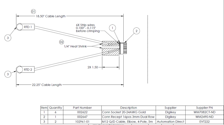
It can be incredibly helpful on a drawing to call out with a pointer where material should be used on the drawing.


  • Best practice is to callout items numbers on the physical layout, usually with a circled BOM item#.
  • This makes it much easier to identify which parts should be used together and where they should be used.
  • It’s also sometimes helpful to simply write part numbers directly next to items on a drawing.


Bills of Material

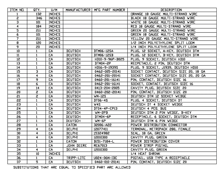
  • Best practice is to give a table with item numbers, those item numbers can be used for material callouts in the drawing.
  • Manufacturer part numbers for all components is ideal for all parts, except maybe where we stock generics like UL wire and heatshrink
  • We can certainly help with simplifying a BOM, but knowing exactly what materials we’re expected to use can be very helpful!


Custom Cable Assembly

The First Article Process

The First Article Process is a crucial part of production requirements at Technical Cable Applications.  The process confirms that an assembly has been designed as intended and that documentation is complete and interpreted correctly.  It verifies that proper assembly techniques and tooling are used and assures that later builds of product are produced without variation.

Quotation

At TCA the first article process starts before an order is ever placed.  During the quote process the customer drawings or specifications are carefully reviewed.   This assures that all the elements for successful production are included.

The bill of materials is evaluated to make certain all the components shown on the drawing are called out and in the correct quantities.   They are looking for any obvious material conflicts such as wire size /terminal compatibility.  A mismatch like this could be because the insulation diameter or wire AWG is too large or too small for a terminal. Discrepancies like this could affect the integrity of the product or damage tooling.

The drawing is checked for clear dimensional criteria and for tolerances that are achievable for cable assemblies.   It is also reviewed for references to any documents or quality standards other than IPC.  If other quality documents are referenced Technical Cable Applications quotations specialists assure those documents are on file.

Tooling and Test Fixtures

During the quote process tooling requirements are checked for all the components.  At Technical Cable Applications the component manufacturers recommendations are checked to assure that the right tools are on hand.   It is verified that mating test fixtures are available for all connectors.  If either of the tooling or test fixtures are not on hand, they will need to be ordered for the build.

Work instructions

Work instructions are created by Technical Cable Applications production engineers.  These seasoned professionals have broad knowledge and training in cable assembly production and quality standards. For cable assemblies this would be to the IPC/WHMA -620B standard.  If there are other production or quality standards called out in the customer documentation the production engineers will obtain a copy and make sure they are part of the process.

The work instruction lists all the machines, tools, fixtures, and materials used.  It contains set up and programming instructions for any equipment used.

A Detailed Accounting

As the production engineers build the first article, they keep a detailed step by step accounting for every process used to build the assembly and in the order it is to be completed.    Special instructions and cautionary notes are often part of the instructions with detailed pictures for each step included.  The completed work instructions are controlled on a central server and every workstation has a computer terminal with to access the information.

In the event the production engineer finds any issue, conflict or has any concerns during the first article build the Sales Specialist is notified, the customer is contacted, and the concern and any resolution are documented.

Test and Inspection

Test and inspection steps are included in the work instruction including inspections where a process might be hidden by a subsequent step.

The finished first articles are sent to the Technical Cable Applications quality department where the assembly undergoes a series of dimensional and quality checks to assure that the assembly meets or exceeds the customer specifications.  The first article assemblies are tested and sent to packaging to be shipped with first article documentation to the customer.

Validation

Once the first article is inspected, tested, and approved by the customer the work instructions are validated by Technical Cable Applications quality personnel.  Production can then be scheduled for the assemblies.

Contact

Technical Cable Applications is an ISO9001:20015 registered company.  Please contact the Technical Cable Applications sales team for help with all of you cable assembly needs.