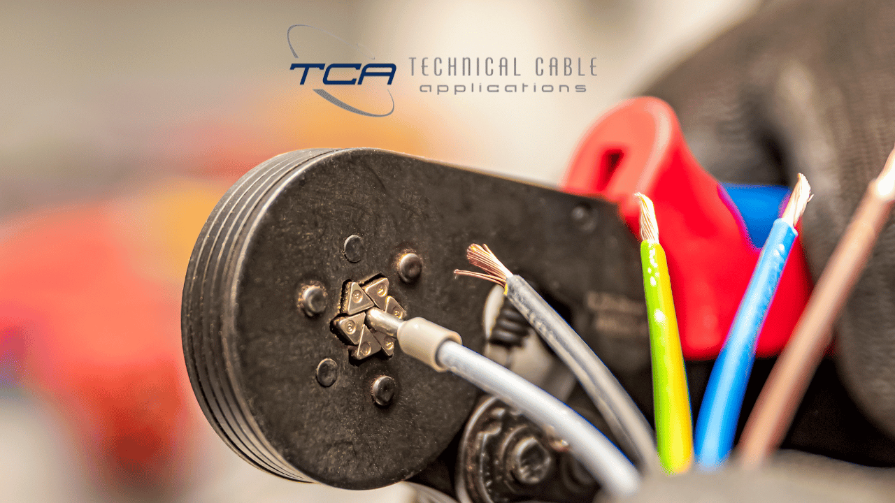
What is a Crimping Tool?
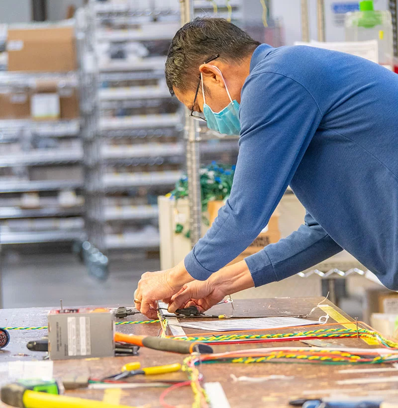
We use all kinds of tools and equipment every day when we create custom cables here at our facility in Washington state. However, one of the most fundamental tasks that any aspiring cable technician must learn to do is wire crimping, which can be done by hand with an applicable crimping tool for the specific task.
What is crimping, and what is a crimping tool used for? To start, crimping is a general term for any kind of manual adjustment to a wire, typically to deform it to create secure connections and/or ensure it fits within the space designated for it.
What is a Crimping Tool Used For?
There are many types of crimping tools and equipment, ranging from small handheld crimper tools for fine adjustments, to gigantic automatic crimping machines intended for large production scale work. What they all have in common is that to properly use them, wire connectors will be inserted into the appropriate die for the desired deformation style, and then the handles or automated machine of the crimping tools will clamp down on the wire and connector, deforming it to the desired shape and sealing the connection. You may also need to use butt connectors to join or extend wires or cables, or shrink connectors to add insulation and waterproofing. These both may require additional crimping tools to get everything secured and deformed just right.
How To Create a Proper Crimp
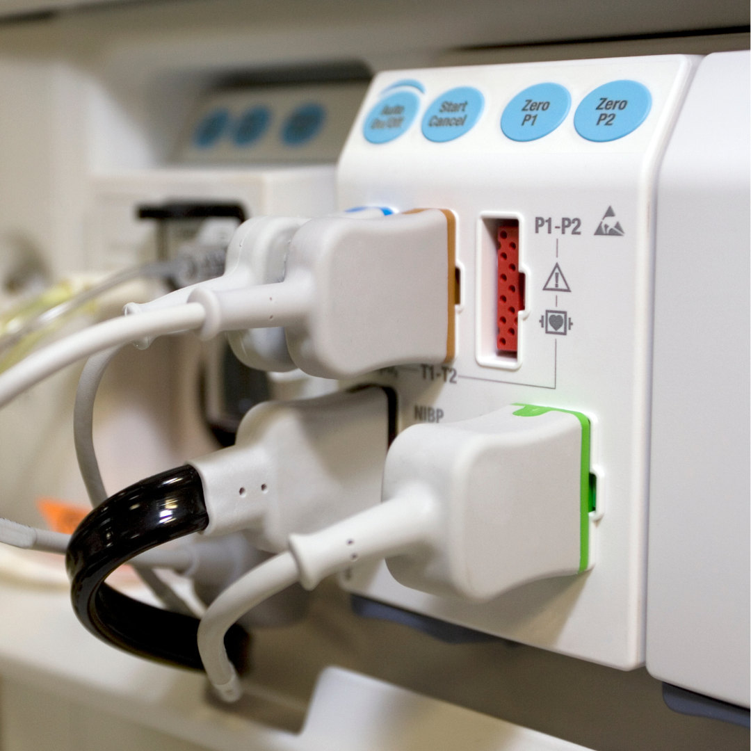
The most important part of using crimping tools is using the correct wire tools for the job. For instance, if you are crimping a coaxial cable by hand, you want to make sure your crimp tool has the appropriate die in it to accommodate the round coaxial connectors’ shape. This applies for crimping network wires, modular wires, or even larger scale items like locomotive battery wire crimping. Without the right die and crimping tools, you run the risk of overforming or underforming the wire, leaving an unstable connection or potentially damaging the connectors and internal components.
What Kinds of Crimping Tools Are There?
- Handheld tools
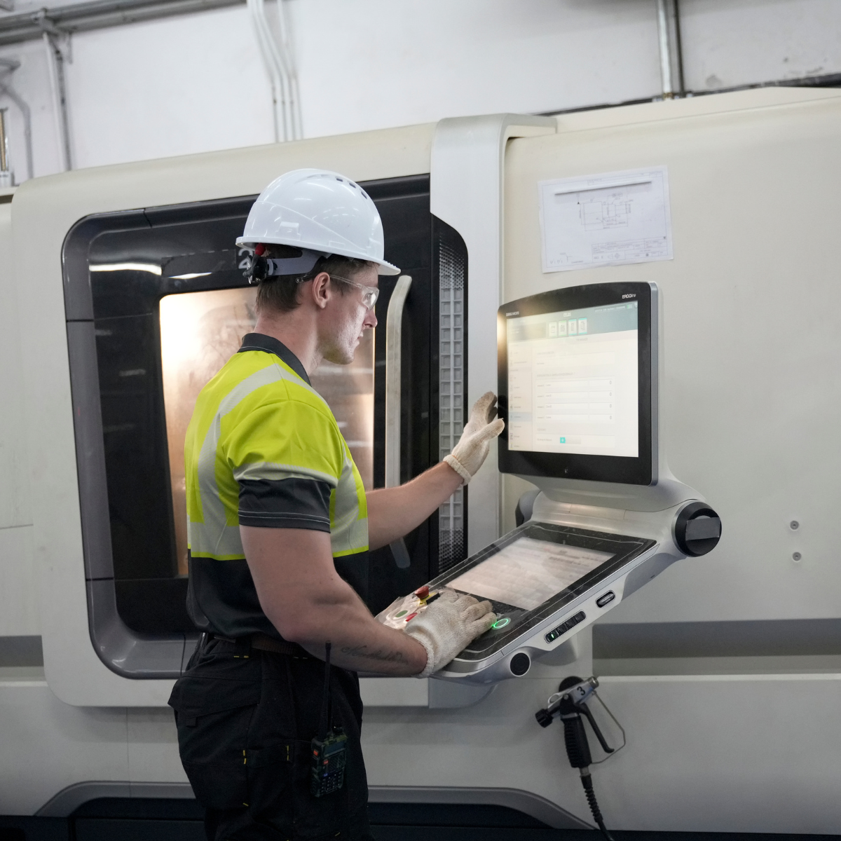
– As previously mentioned, handheld tools let a technician manually crimp individual wires, cables, and connectors to the desired deformation. They come in a variety of sizes and strengths based on how much force is needed to crimp a given wire and connectors combo. - Automated tools
– We use automated crimping machines like our Schleuniger 36SP Crimp Center for very large crimping applications, like for locomotive battery cables where a tremendous amount of force is required due to the size of the cable and connectors. Most handheld crimping tools are insufficient for these larger applications, and many cable manufacturers do not have the capability for them. - Wire cutters and cutting pliers
– While not strictly a crimping tool, cutting wires is often needed to complete the crimp or join two cables together using a butt connector. These can also range from handheld to automated cutters, depending on the size of the wire or cable being cut.
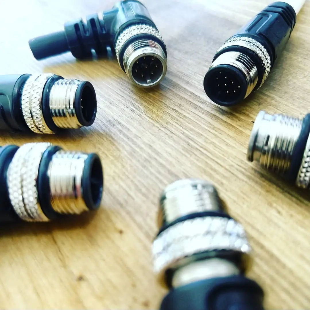
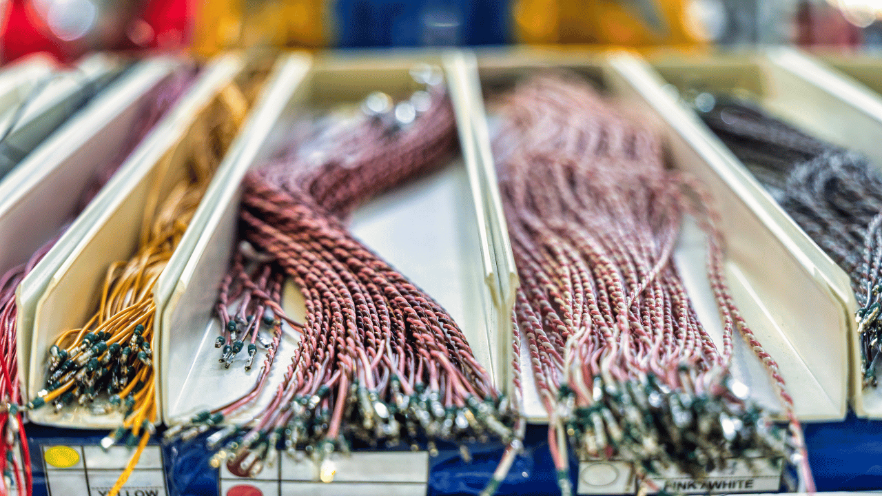
What Types of Wire Can be Crimped?
Essentially all cables and connectors can be crimped in some way, but how much a given combo of the two can deform without causing damage or making the connection less secure rather than more secure can vary wildly. Some cable types like ribbon cables are designed to be extremely flexible, and can be bent or deformed into all kinds of shapes without losing connection quality. In contrast, highly shielded or armored cables are more resistant to crimping due to the protective layers put around them, so crimping may need to be done prior to the application of shielding the cable, and the shield applied to the deformed cable rather than trying to crimp it afterwards with crimping tools that can’t accommodate the extra size.
How to Avoid Damaging Connectors While Using Crimping Tool – Avoid Pliers
The most crucial thing to avoid when working with connectors is ill fitting or sub-optimal tools for the specific connector type. You should have a die in your crimping tool that will provide the desired deformation for the specific connector and wire styles in use, and will fit the sizing. It may be tempting to use basic pliers to manually bend the wire and connector to the desired shape or twist, but this is very likely to damage the internal components, or cause the wire and connector to be out of spec. It’s generally best to only use plier tools for minor adjustments.