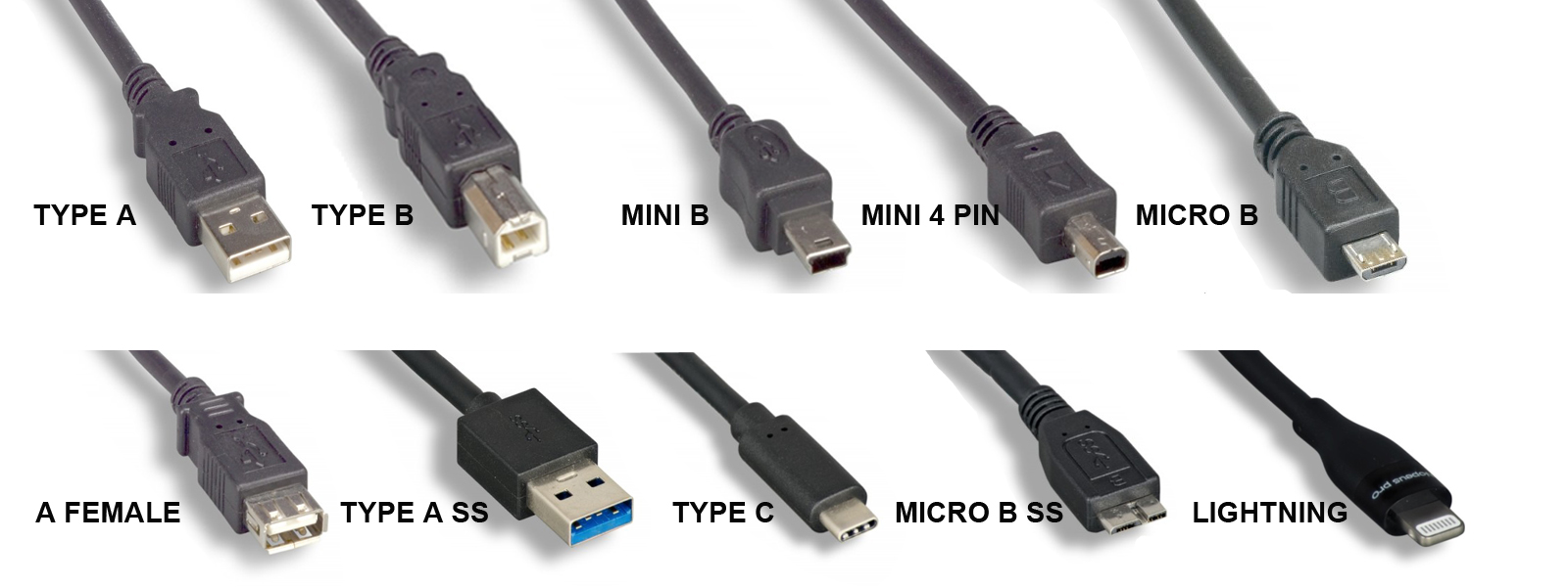
A USB cable assembly is a finished cable built to a USB specification, with a connector on each end, that carries data, power, or both between devices. USB cable assemblies are in nearly every product category, from consumer electronics to medical devices, industrial controls, and test equipment. Choosing the right one means matching the connectors, the USB data rate, the length, the current rating, and the cable’s construction to where it will be used.
This guide covers how USB cable assemblies are built, the USB standards and connector types in use today, length and power limits, and what to specify when you order a custom assembly. Technical Cable Applications (TCA) manufactures custom and OEM USB cable assemblies, from Type-A to USB-C.
What Is a USB Cable Assembly?
“USB cable” and “USB cable assembly” often mean the same thing. In manufacturing, “assembly” stresses that the product is built from separate parts: bulk cable, connectors, and the molding or hardware that joins them. It’s terminated and tested as a finished unit.
An off-the-shelf USB cable is a fixed design: standard connectors, a few stock lengths, a general-purpose jacket. A custom USB cable assembly is built to a drawing. The buyer specifies the connector ends and orientation, exact length, wire gauge, shielding, jacket material, overmold shape, labeling, and testing. OEMs use custom assemblies when a stock cable is the wrong length, won’t fit the enclosure, can’t survive the environment, or needs a connector combination nobody stocks.
Components of a USB Cable Assembly
Each end has a plug (male) or receptacle (female) in one of the USB connector families: Standard-A, Standard-B, Mini-B, Micro-B, or USB Type-C. The connector determines which ports the cable fits and limits which USB data rates it can support. USB-C is the only connector that supports USB 3.2 Gen 2×2 (20 Gbps) and USB4.
Conductors
The wires inside depend on the USB version the cable supports:
- USB 2.0: four conductors: VBUS (+5 V power), ground, and a twisted data pair (D+ and D−). The data pair is designed for 90 Ω differential impedance. Data wires are typically 28 AWG. Power wires range from 28 AWG to 20 AWG, and a heavier gauge allows a longer cable or more current.
- USB 3.x on Standard-A, Standard-B, or Micro-B: the four USB 2.0 conductors plus two shielded SuperSpeed differential pairs (one transmit, one receive) and a drain wire.
- USB-C to USB-C: a full-featured cable adds four high-speed differential pairs plus the configuration channel (CC), sideband use (SBU) lines, and VCONN, which powers the electronic marker chip described below. A USB 2.0-only USB-C cable leaves out the high-speed pairs.
Shielding
High-speed USB cables are shielded to contain electromagnetic interference (EMI) and protect the signal from outside noise. A common construction is an aluminum-foil shield under a tinned-copper braid, with a drain wire bonded to the connector shell. SuperSpeed pairs are usually shielded individually as well. Shielding matters more in electrically noisy places such as factories, near motors and drives, or around medical and RF equipment.
Jacket
The outer jacket protects the conductors from abrasion, chemicals, temperature, and flexing. PVC is the general-purpose standard. PUR (polyurethane) and TPE resist oil, abrasion, and repeated flexing better, which suits machinery and cable carriers. Low-smoke zero-halogen (LSZH) jackets are specified where smoke toxicity is a concern.
Overmold, Backshell, and Strain Relief
The joint between cable and connector is the most common failure point. Overmolding encases the termination in molded plastic to seal it and give it a shaped strain relief. Metal or die-cast backshells add mechanical strength and EMI protection, and some include thumbscrews or latches to lock the plug in place.
Electronic Marker (USB-C)
Many USB-C cables include an electronic marker (e-marker) chip that reports the cable’s capabilities, such as current rating and supported data rate, to connected devices. The USB Type-C specification requires an e-marker in cables rated for 5 A and in full-featured USB-C to USB-C cables. Without one, a device assumes the cable is limited to 3 A.
USB Standards and Data Rates
USB was introduced in 1996, and each major revision raised the maximum data rate. The USB Implementers Forum (USB-IF) has renamed several versions over time. For example, the original USB 3.0 has also been called USB 3.1 Gen 1 and USB 3.2 Gen 1. Since 2022, USB-IF has recommended that products be labeled by speed (“USB 5Gbps,” “USB 10Gbps,” and so on) rather than by version number.
| Version (later names) | Max data rate | Speed-based label | Connectors | Year |
|---|---|---|---|---|
| USB 1.0 / 1.1 | 1.5 Mbps (Low Speed), 12 Mbps (Full Speed) | n/a | Standard-A, Standard-B | 1996 / 1998 |
| USB 2.0 | 480 Mbps (High Speed) | n/a | Standard-A/B, Mini, Micro, USB-C | 2000 |
| USB 3.0 (USB 3.1 Gen 1, USB 3.2 Gen 1) | 5 Gbps | USB 5Gbps | Standard-A/B SuperSpeed, Micro-B SuperSpeed, USB-C | 2008 |
| USB 3.1 Gen 2 (USB 3.2 Gen 2) | 10 Gbps | USB 10Gbps | Standard-A SuperSpeed, USB-C | 2013 |
| USB 3.2 Gen 2×2 | 20 Gbps | USB 20Gbps | USB-C only | 2017 |
| USB4 (Version 1.0) | 20 or 40 Gbps | USB 20Gbps / USB 40Gbps | USB-C only | 2019 |
| USB4 Version 2.0 | 80 Gbps; up to 120 Gbps one way in asymmetric mode | USB 80Gbps | USB-C only | 2022 |
USB 2.0 remains the most common interface for peripherals, sensors, and embedded devices that don’t need high bandwidth, because it’s inexpensive and tolerates longer cable runs. The 5 Gbps to 20 Gbps tiers cover storage, cameras, and docking. USB4 serves high-bandwidth uses such as external displays and fast storage.
USB Connector Types
The connector and the data rate are separate choices. A USB-C cable can be wired for USB 2.0 only or for USB4, so specify both. For help telling connectors apart by sight, see our guide on how to identify USB cable types.
| Connector | Versions | Typical use today | Introduced |
|---|---|---|---|
| Standard-A | USB 1.x, 2.0; SuperSpeed version (9-pin) for USB 3.x | Host side of most legacy cables: computers, chargers, hubs | 1996 |
| Standard-B | USB 1.x, 2.0; SuperSpeed version for USB 3.x | Printers, scanners, audio interfaces, instruments, industrial equipment | 1996 |
| Mini-B | USB 2.0 | Older cameras, GPS units, MP3 players; still found on some industrial and test equipment | ~2000 |
| Mini-A / Mini-AB | USB 2.0 (On-The-Go) | Rarely used; deprecated by USB-IF in 2007 | ~2001 |
| Micro-B | USB 2.0; SuperSpeed version (10-pin, wider) for USB 3.x | Older Android phones and accessories; Micro-B SuperSpeed on many external hard drives | 2007 |
| Micro-A / Micro-AB | USB 2.0 (On-The-Go) | Let a mobile device act as host; uncommon | 2007 |
| USB Type-C | USB 2.0 through USB4; USB Power Delivery | Current standard for phones, laptops, tablets, and new devices; reversible | 2014 |
Apple’s Lightning connector (2012) isn’t a USB-IF connector, though USB-to-Lightning cables are common. Apple has moved its newer devices to USB-C, and since 28 December 2024 the EU has required USB-C charging ports on phones and many other portable devices sold there.
USB Cable Length Limits
Signal loss rises with frequency, so the faster the data rate, the shorter a passive cable can be. These are the usual limits for passive cables:
| Cable type | Typical maximum length |
|---|---|
| USB 2.0 (Standard, Mini, Micro connectors) | 5 m |
| USB 3.x, Standard-A/B or Micro-B, 5 Gbps | About 3 m in practice (the spec sets a loss budget, not a length) |
| USB-C to USB-C, USB 2.0 | 4 m |
| USB-C to USB-C, 5 Gbps | 2 m |
| USB-C to USB-C, 10 Gbps | 1 m |
| USB-C to USB-C, USB4 40 Gbps | 0.8 m |
USB-C lengths are the recommended maximums in the USB Type-C specification. Longer runs need active cables, which use electronics in the connector housing to regenerate the signal, or active optical cables (AOCs), which carry data over fiber. Powered hubs and repeaters are another option.
Power and Current Ratings
USB cable assemblies carry power as well as data, so the conductors have to be sized for the current.
- Default USB power: 500 mA at 5 V for USB 2.0 ports and 900 mA for USB 3.x ports.
- Battery Charging (BC 1.2): up to 1.5 A at 5 V from dedicated charging ports.
- USB Type-C current: 1.5 A or 3 A at 5 V, advertised over the CC line.
- USB Power Delivery (PD): negotiates higher voltages. Standard Power Range reaches 100 W (20 V at 5 A). Extended Power Range, added in PD 3.1 (2021), reaches 240 W (48 V at 5 A).
Every USB-C cable must handle at least 3 A. Delivering more than 60 W (above 3 A) takes a 5 A-rated cable with an e-marker. In a custom assembly, the power-conductor gauge, the cable length, and the allowable voltage drop are designed together.
Common USB Cable Assembly Configurations
- Straight-through cables: a standard connector on each end, such as USB-A to USB-C or USB-A to Micro-B.
- Right-angle and up/down-angle connectors: for tight enclosures and cable routing.
- Panel-mount and bulkhead extensions: bring a USB port through an enclosure wall to a front panel.
- Locking and screw-retention connectors: thumbscrews, latches, or threaded couplings keep the plug seated under vibration.
- Sealed connectors: IP-rated USB connectors and sealed overmolds for washdown, outdoor, or dusty environments.
- Y-cables and split cables: separate power and data, or feed power from two ports.
- Adapter cables: USB to serial (RS-232/RS-485), USB to Ethernet, USB to HDMI, and other protocol converters.
- Bare or pigtail ends: a USB connector on one end and stripped, tinned, or crimped leads on the other for wiring to a board or terminal block.
For machinery, automation, and other harsh environments, see our overview of industrial USB cables.
How to Specify a Custom USB Cable Assembly
A complete specification avoids rework and gets an accurate quote faster. Define the following:
- Connector ends: connector type, gender, and orientation (straight, right-angle) for each end.
- USB version and data rate: USB 2.0, 5/10/20 Gbps, or USB4. This sets the conductor count and shielding.
- Length and tolerance: keep within the limits above, or plan for an active solution.
- Current and voltage: the maximum current and whether USB Power Delivery or an e-marker is needed.
- Wire gauge: especially for the power conductors on longer cables.
- Shielding: foil, braid, or both, and how the shield terminates to the connector shell.
- Jacket: material (PVC, PUR, TPE, LSZH), color, outer diameter, and flex requirements.
- Environment: temperature range, chemical or oil exposure, UV, moisture or ingress rating, and vibration.
- Termination and strain relief: overmold shape, backshell, locking hardware.
- Compliance: for example RoHS, REACH, UL listing, or USB-IF certification if the product will carry USB logos.
- Labeling and packaging: part-number labels, heat-shrink markers, bagging, and coiling.
- Testing: the electrical tests required and any documentation that must ship with each lot.
- Quantity: prototype, pilot, and production volumes.
A drawing with the full pinout is the fastest route to a quote. Learn more about TCA’s custom USB cable assemblies.
Testing and Quality
USB cable assemblies are usually tested for continuity, opens, and shorts on every conductor. Many specifications add insulation resistance or hipot testing. High-speed assemblies may also need signal-integrity testing, such as differential impedance, insertion loss, and crosstalk, to confirm the cable meets its data rate at its length. Products that will display USB-IF logos must pass USB-IF compliance testing.
TCA is ISO 9001:2015 certified for custom and OEM cable assembly, and holds UL cable assembly certification for the United States and Canada.
Custom Requirements
In addition to our OEM offerings, Technical Cable Applications’ skilled specialists are ready to help with any custom cable assembly requirements you might have. TCA stocks cables, connectors, and materials by the thousands and can custom build dies and molds not on hand.
Please contact the TCA Technical Sales Team for assistance with all your cable assembly needs by reaching out to [email protected] or giving us a call!
*Please provide cable drawings and all documentation available when contacting us so we can quickly give you an accurate quote. We will do our best to research specifications and materials if a drawing is not available, but if no documentation exists that may need to be created first before we can proceed.