Technical Cable Applications was founded in 2002 in Auburn, WA. Since then, we have grown to serve customers all over the United States, North America, and internationally. Our staff has expanded tenfold since our original startup along with our facility’s real estate, reflecting our commitment to growth and excellence.
Creating an assembly drawing that’s easy to understand and interpret as a blueprint for your cable assembly needs can be pretty difficult, so here are the basics if you’re learning, and some additional pointers to help you improve your cable drawing capabilities at the end too.
What Should My Blueprint Include?
Here are the most basic components that fabrication drawings typically cover for the physical layout and dimensions of the cable assembly. This section will be most helpful if you’re completely new to the process of drawings cable assembly, and are trying to draw a custom cable assembly drawing or OEM electrical cable for the first time.
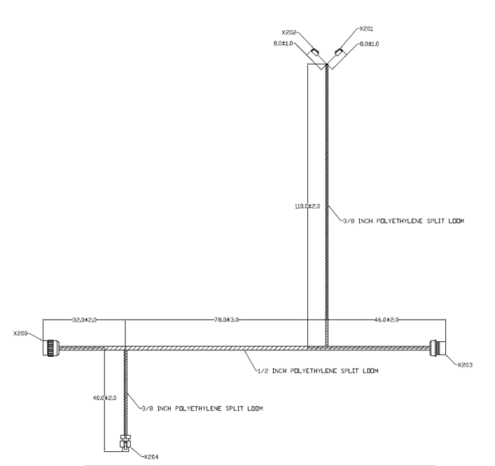
Specify the length of the entire cable assembly or wiring harness, and individual wire or cable lengths in exact measurements
– Any extra electrical or cable components that will be manufactured should also have length specified
– Branches and breakout points should also have measurements specified
Note the placement of all cable connectors and specifications of which mating orientation is used where for interface cable
– It should be clear whether male or female connectors are being used along with the general type of cable connector
– Ideally cable connectors will have exact sizing and measurements as well noted here to ensure that the right ones are used
Include any details about cable strength and bending needs
– Minimum cable bend radius is a common specification as over-bending will damage many cable connectors and cable types
– Strain relief locations, these are typically the areas that are least likely to break when the cable is under pressure
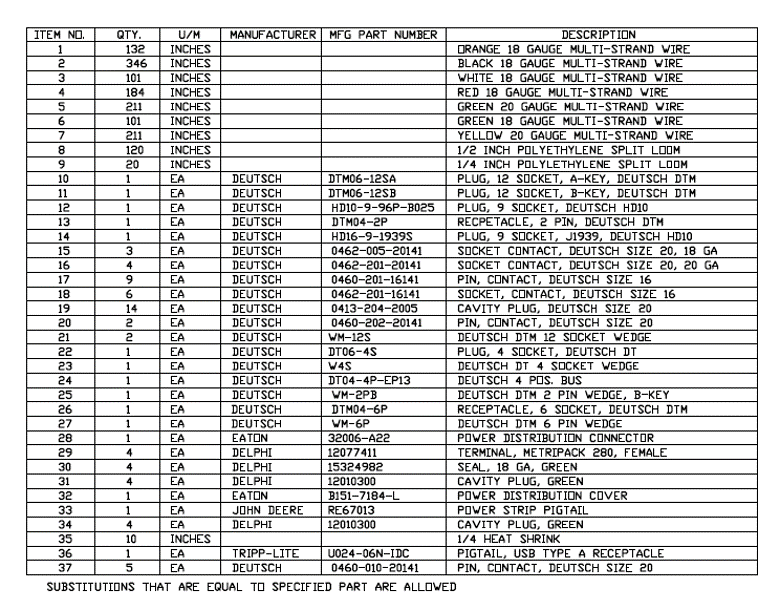
More specific components like connector pinouts, wiring details, assembly sequences, cable kits, etc. may only be needed later in prototyping, or not at all if the cable assembly is simple enough to examine and build.
Drawing Assembly Specifications: Best Practices for Cable Drawings
Here are some additional tips for how to optimize your cable assembly drawing and what is most important to include.
Right angles are easiest to interpret but not always necessary.
It should be clear where to measure dimensions from, like end of connector or back of connector (dimension lines are great!)
Dimensions should be measurable from places which can be measured on a completed assembly (wire cut lengths can be hard to inspect). We will 100% check these in final inspection.
Length tolerances should be wide enough to be easy to manufacture+/-5% is great. Use a -0 tolerance if nominal length is the shortest acceptable. (IPC has guidelines for this as well)
Labels and heatshrink should appear on the drawing with dimensions and tolerances (or specified as “about” or “TYP”)
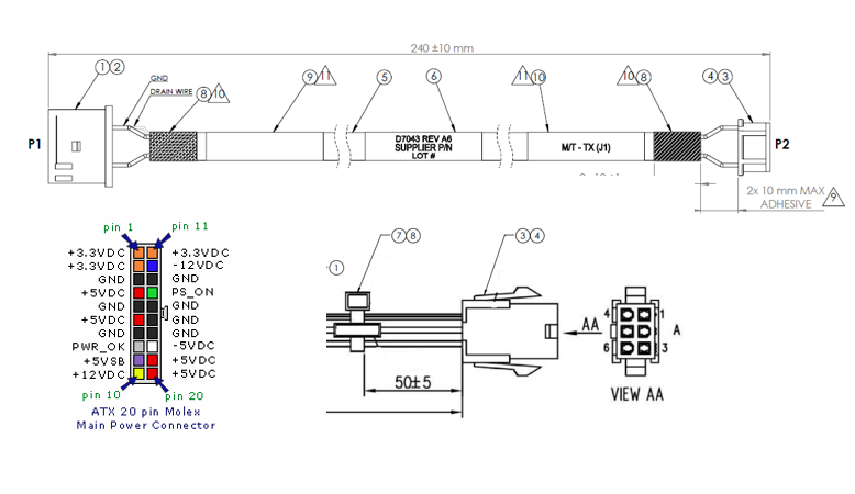
Specifying the pinout of the connector, especially with colors, is very helpful. Best practice is 3rd angle projection of the connector face.
 This makes it much easier to identify which parts should be used together and where they should be used.
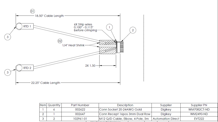 This makes it much easier to identify which parts should be used together and where they should be used.